

Michigan Mighty Mite is a QRPP CW transmitter that's easy to built, with a rated power from 200mW to 800mW.

QRP radio operators try to get maximum range out of minimal power. This term comes from the QRP Q-code, which means "reduce power." For years, people have built some very low-cost radios for this purp...

The Sputnik regenerative receiver was designed for the 40m amateur radio band, the perfect project for beginners in homebrew radio receivers.

USDX USDR HF QRP SDR Transceiver SSB/CW Transceiver 8-Band 5W DSP SDR Black Shell US Plug With Mic\n\nSoftware: https://github.com/threeme3/QCX-SSB/tree/feature-rx-improved\n\nDescription: This is a shortwave druse ssb/cw transceiver. It has 1602 screen, built-in battery, equipped with charger, built-in microphone, built-in speaker! It can be connected to an auto key and can be cw decoded.\n\nFunction list: - Simple, interesting and versatile cxp ssb HF transceiver with built-in dsp and sdr functions - EER electronic level driven SSB launch stage - 13.8v power supply provides about 10w ssb output -Full mode support: usb, lsb, cw, am, fm -dsp filter: password 4000, 2500, 1700, 500, 200, 100, 50hz - DSP Function: Auto Gain Control (AGC), Noise Reduction (NR), Voice Trigger, Xmit Voice Trigger (VOX), Attenuator RX Attenuator (ATT), TX Noise gate, TX driver control, volume control, dbm/s meter - Sideband Reverse SSB/Carrier Suppression: better than -45dbc, imd3 (two tone) -33dbc, reception: better than -50dbc -Multi-band support, continuously adjustable in 160m-10m frequency band (and 20khz..99mhz performance loss) -Open source, integrated firmware for Arduino IDE; allows experimentation, can add new functions, can share contributions via github, software complexity: 2000 lines of code -Software based VOX can be used as a quick and full raid (QSK and Semi-QSK operation), or to assist in running in digital mode (no cat or ptt interface) for rx/tx switching, external delayed ptt output control tx/pa -Simple installation modification with 8 component changes and 8 wires -Lightweight and cost-effective transceiver: thanks to the level and eer transmitter, it has high energy efficiency (no bulky heat sink needed) and simple Design (no complex balanced linear power amplifiers required) -SSB transmitter stage entirely based on digital and software: by controlling the phase of the PLL SI5351 (through the small frequency shift of I2C above 800kbit/s) and the amplitude of the PA (through the PWM of PWM) to sample the microphone input and reconstruct the ssb signal. Pa key shaping circuit)\n\n Port introduction: -Charge: Built-in lithium battery charging port and you can only use the charger provided! It is forbidden to use other chargers! -Switch: off to turn off. Bat: Built-in battery power supply. 13.8: external power supply -DC13.8v/3a: external power supply port -Key: Automatic key body connection (A, B, single key) -Pa: external power amplifier, PTT signal -Microphone: External microphone port -Uart: serial communication port (osmo compatible) -Spk: external speaker\n\nPackage included: 1 x Transceiver 1 x Power Adapter 1 x Mic 1 x 3 in 1 screwdriver
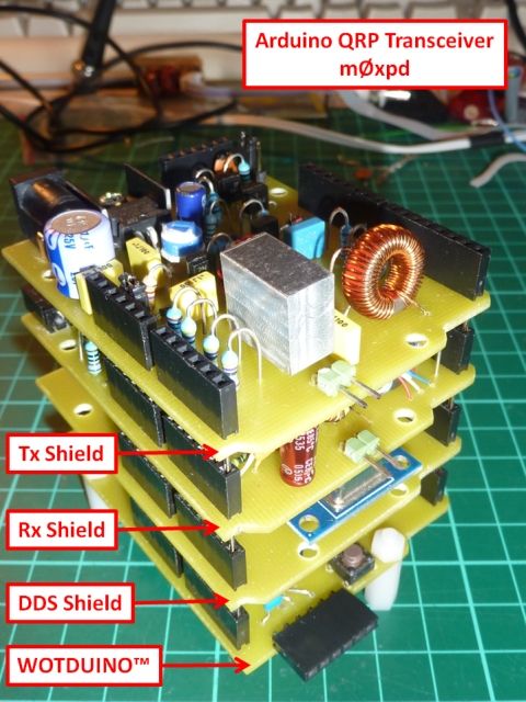
Meet my new rig - a QRP CW Transceiver for the lower HF bands, built around the Arduino "open-source electronics prototyping platform". Readers have seen in recent posts how I developed a multi-mode beacon using the Arduino - but that was only a waypoint on the journey towards a full ham radio transceiver. We started the journey with my homebrew version of the Arduino - the "Wotduino" and then wrote code to make the Wotduino work as a Keyer. Then the Wotduino was given the ability to generate radio frequency signals, using an AD9850 DDS chip on an inexpensive module from eBay, mounted on a homebrew DDS shield. Then we added a QRP transmitter, enabling the system to work as a beacon. The last leg on the journey is a receiver, as seen in the photo above. My new receiver is derived directly from the Rx stage of Roy Lewallen, w7el's beautiful and definitive Optimised Transceiver for 40m. I've used this as a start point before, both in the Rx for my "Funster Plus" rig and as a QRSS/WSPR receiver. My new circuit is implemented on an Arduino shield, as seen below... The signal path from the antenna goes to a double-balanced modulator, where it is mixed with the LO signal from the DDS module. This generates audio frequency (by direct conversion), which is amplified in a common base stage and then passed through a 2nd-order Sallen-Key bandbass filter. Next, a further gain stage controls volume and limits the voltage swing (ironically using the same back-to-back diode method exploited in the Tube Screamer). The receiver is muted during transmission by a FET pass-gate, under the control of the Arduino. Finally, a little audio power stage drives headphones or small speakers. The receiver sits in the stack of "shields" on top of the Wotduino... All this adds up to a viable transceiver, as explained in the block diagram of "architecture" below... The Wotduino controls everything through what we might call a "control bus" formed by the stackable header plugs on either side of the boards. To this bus is connected a paddle and a straight key, interacting with the keyer code. The DDS module also sits on the control bus, through which it is instructed to generate the appropriate frequency. This RF is carried on an additional "RF bus", implemented on a line of 6-way stackable headers which link the DDS, Tx and Rx shields. The DDS signal is amplified and buffered by a circuit on the Tx shield, from where it is passed to the new Rx shield by another line on the RF bus. Also hanging off the control bus is a display to show the operating frequency. This is an old 12-character, 7-segment serial input LCD module which I picked up at some long forgotten rally for pennies. The frequency is adjusted using a rotary encoder - which also selects the band. The rotary encoder has a push-button, which allows me to adjust the frequency in 10Hz, 100Hz or 1kHz increments (10Hz is the lowest resolution necessary, whilst 1kHz lets me scan across the band - or change bands - quickly). When you adjust the frequency above the top band edge (more exactly above the top of the CW segment of the band), it automatically steps up to the next band. Similarly for downward QSYs. Here's the rig in the habitual lashed-up state (perhaps I should say "Kludged" or "Kloodged" state) on the bench, back in the day when I was still using a potentiometer for frequency adjustment... It is connected to speakers from a roadkill computer and an old straight key for testing. I don't know about you, but whenever there's a viable rig testing on the bench, I just can't keep my hand off the key and the antenna coupled to a dummy load - I always end up having a QSO. So much for testing! In spite of all my high intentions of making a case, etc, etc, I couldn't stop myself from answering Andy dm5mu in Leipzig and getting a 559. Then Miroslav, yu1dw, in Cicevac, Serbia for a 579. Not bad for my first two attempts on 40m with my 500mW. After these initial QSOs I added a "send/return" connection so I could route the audio signal through my variable bandwidth CW filter (SPRAT v.146 p20), which makes the rig much easier to use when the bands are noisy or congested. The rig is set to cover top band through 20m - but so far I've only had QSOs on 80 (including Ian, g3roo's QRSnet) and 40. Right - now let's see about some kind of enclosure to pretty the whole thing up a bit... ...-.- de m0xpd

Michigan Mighty Mite is a QRPP CW transmitter that's easy to built, with a rated power from 200mW to 800mW.

Basic multi-z antenna tuner for QRP. Easy to tune low-z and high-z antennas. This is just an experiment while testing it with my 40m EFHW antenna.

Shimizu SS-105S

QRP 150 W 1,6–50 MHz SWR HF Kurzwellen-Stehwellenmessgerät SWR/Leistungsmessgerät FM/AM/CW/SSB 150 W QRP, minimale Anzeigeleistung 0,25 W, minimale Tuning-Leistung 2,5 W, vorherige 100 W minimale Tuning-Leistung 10 W, jetzt kann dieser QRP verschiedene Leistungsstationen erfüllen 5 Schnittstellen-Anzeigemodi. Dynamische Simulationsanzeigeleiste. Wechseln Sie zwischen Normalmodus und Spitzenwerthaltemodus. Gemäß dem Anpassungsalgorithmus der Erkennungsdiodeneigenschaften ist die Genauigkeit besser als ±5 %. Hochgeschwindigkeits-Durchschnittserkennungsmethode, Echtzeit-Effizienzanzeige. Intermittierender Summeralarm, wenn die stehende Welle größer als 2,0 ist, und kontinuierlicher Summeralarm, wenn die stehende Welle größer als 3,0 ist. Kompatibel mit dem Open-Source-Softwarecode von g8gyw. Sie können den Code kostenlos ändern, um mehr Spaß zu haben. Der eingebaute Lithium-Akku kann mehr als 50 Stunden am Stück genutzt werden. Spezifikationen: Frequenzbereich: 1,6–50 MHz Leistungsmessbereich: 0,5 W-150 W Messbereich für stehende Wellen: 1,0–99,9 Einfügedämpfung: <0,12 dB Stehende Welle einfügen: 1,6–30 MHz ≤ 1,02; 30–50 MHz ≤ 1,05 Messgenauigkeit: besser als ±5 % Impedanz: 50 Ω Stehwellenalarm: ≥2,0 intermittierender Alarm, ≥3,0 kontinuierlicher Alarm (mit Abschaltfunktion) HF-Schnittstellentyp: SL16-M Anzeigeinhalt: Vorwärtsleistung; stehende Welle; Antennenleistung; Effizienz. Stromversorgung: Eingebauter wiederaufladbarer Lithium-Akku mit 3,7 V/900 mAh oder USB Typ C Stromverbrauch beim Herunterfahren: <0,1 uA Bildschirmgröße: 0,96 Zoll Bildschirmtyp: OLED Datenkommunikation: USB Typ-C Abmessungen: 88 mm * 38 mm * 64 mm (ohne den hervorstehenden Teil) Nettogewicht der gesamten Maschine: 190 g Besondere Erinnerung: Die oben genannten Parameter werden alle mit professionellen Instrumenten gemessen und sind wahr und effektiv. 150 W kontinuierliche Erkennung; Bei mehr als 500 W werden die Erkennungskomponenten beschädigt. kurze Einleitung: Langes Drücken auf Ein/Aus, kurzes Drücken auf Ein/Aus, um die Anzeigeschnittstelle umzuschalten, doppelklicken Sie auf den Stehwellen-Alarmschalter; Dreifachklick, um zwischen Normalmodus und Peak-Hold-Modus zu wechseln. Es gibt insgesamt 5 Anzeigeschnittstellen, die automatisch gespeichert und beim nächsten Mal automatisch abgerufen werden. Das rote Ladelicht bedeutet, dass das Licht aus ist, wenn es vollständig aufgeladen ist. Lieferinhalt: 1 x Gastgeber 1 x Typ-C-Ladekabel 1 x Maschineneckenpolster Garantie: Rücksendungen: Kunden haben das Recht, innerhalb von 60 Tagen nach Erhalt des Produkts eine Rücksendung zu beantragen 24-Stunden-Experte online: Lösen Sie Ihre Installations- und Produktprobleme

This looks like something that fell out of the sky at Roswell, New Mexico, 1947. It is a QRP rig capable of both transmitting and receiving on the 80, 40 and 30 meter ham bands. This quirky little radio works great! You will receive a full schematic of the circuitry, along with parts values, coil data, etc. No manual or assembly instructions are included, so you will need a fair degree of technical skills and some previous experience in constructing similar radios. The radio uses a pair of VHF dual pentode tubes. The 832 functions as a twinplex pentode regen receiver, while the 815 is the cw transmitter. You'll need a well filtered 25 volt source capable of at least 1 amp dc for the filament and regen circuits. Ideally something that will deliver about 1.25 amps continuous duty is best. A separate input line on the wiring harness feeds the cw transmitter plate circuit. At 50 volts dc I get just under one watt output. You can easily double or triple the power out by using a 75 to 100 volt dc source to power the transmitter. I can get about 170 milliwatts output just using one 25 volt power source, connected in parallel, for both receiver and transmitter. The regen radio works strictly off the 25 volt source, so you may opt to run the receiver alone, with no power applied to the transmitter, other than the common filament voltage. These are 12 volt filament tubes, so since both pull 0.8 amps I connected the filaments in series. So you'll need a 25 volt dc source for the filaments. The receiver works wonderfully with the 25 volt filament line as its operating voltage for the regen detector and audio amp circuits of the 832 tube. So, again, no need to apply transmitter power voltage if you simply want to run the regen radio by itself with a 25 volt dc source. Regenerative receivers will virtually always sound best if powered with a battery source. The transmitter tank circuit employs the double parallel/series method, just like the old Paraset Spy radio. It works great and can load into any reasonable length of wire for an antenna. The radio has a send/receive switch which transfers the antenna so that one antenna functions for both send and receive. Obviously you will need a ham radio license to put this radio on the air. Controls are main and fine tuning, antenna coupling and a regen pot for the receiver, plus PA and antenna load tuning for the transmitter. The regen pot also has a power on/off switch. I guarantee this radio will work if properly, with appropriate power supply and a good antenna. These old vhf power pentode tubes make great regen receiver/transmitter tubes. Shipping to the US only.

Michigan Mighty Mite is a QRPP CW transmitter that's easy to built, with a rated power from 200mW to 800mW.

Michigan Mighty Mite is a QRPP CW transmitter that's easy to built, with a rated power from 200mW to 800mW.

Kang.K.P.S. blog about minimalist QRP, Homebrewing, QRP circuits, Transmitter, receiver, transceivers, amateur radio, ham radio, related.

QRP CW operation is like fly fishing. It takes skill and patience and very little equipment. Here is this addictive activity in a nutshell.

TEN-TEC Century 21 A second HF rig has somehow found its way into my home. Ten-Tec Century / 21 CW Only Transceiver Since getting back into HAM radio with my focus now on CW and QRP I find that many of my contacts use old and/or homebrew equipment. Maybe it's because I often call CQ with my straight key rather than paddles that results in most answers to my CQ being operators using a straight key or a bug. It seems these operators tend to not use the latest piece of shiny gear, which made me an anomaly; sending with a straight key while using my SDR-in-a-box like the Elecraft KX3. Maybe for this reason I've found myself being drawn to less sophisticated types of equipment. I'm not talking about wanting to go back to spark gap and gravity batteries, but sometimes the KX3 is just too easy to use. In the same way that I'd prefer to send CW using a Straight Key to a keyboard since it's a greater challenge, I think that the older, less sophisticated equipment can bring more satisfaction to the hobby. Vintage... like bell bottom jeans and corduroys Now don't get me wrong, I'm not suggesting that the only "real" radios are those with discreet components or tubes, nor am I saying no key but a straight key. I'm just moving through some stages of the hobby that I missed because I didn't grow up with this older equipment and I think the challenges can be fun to learn and operate. I didn't get into Ham radio until 2006 and the commonly available used equipment of the time was microprocessor controlled rigs with digital displays, optical encoders, DSP filters and seemingly endless menus for configuration. I went through a few HF radios over a couple of years: a Yaesu FT-857, ICOM 730 and lastly, a ICOM 746 Pro, before I sold the radios and dropped out of the hobby. At the time none of those rigs held any "magic" for me, they were just tools with increasing levels of functionality and ease of use. However the ICOM 730 did hold copious amounts of stale cigarette smoke and nicotine from the previous operator that it would release into my room as it warmed up. Not really magic, more of a non-corporeal element let's say. If you've read my earlier posts you may recall that although I like my Elecraft KX3 immensely I have some strange fondness for TEN-TEC equipment. Ten-Tec has made some quirky radios with legendary full break-in QSK and supposedly smooth, quiet receivers for CW operators for a few decades now. So when a Craigslist posting leaped into my browser window (I don't know how that happened) advertising a seemingly pristine late-70s rig that had supposedly been reworked to a perfection, all for $140, I just couldn't pass it up... well at least the price in the ad was accurate. The Ten-Tec Century 21 is an interesting transceiver. In the simplest sense it was an ideal radio for the Novice Licensed HAM operator of the 1970s. It is a CW only transmitter. It doesn't require fiddling with a resonant tank circuit of the typical tube radios of the era to work out resonance. It has a built-in power supply that runs off 115-120v mains. It doesn't use a superheterodyne receiver but a direct conversion receiver (Ten-Tec called it a double direct conversion receiver). This resulted in a simplified design and good selectivity but without the IF there is no AGC so be ready to work those RF/AF gain knobs. It also has easy band changing and nice filtering. From web searches and reviews its most common problem is a PTO that has to be rebuilt every few years. The Ham I purchased mine from said it had been rebuilt. It doesn't slip (yet) but it's kinda stiff so I expect a PTO rebuild to be in my future. I spoke with a ham I work with who has rebuilt one and he said it's not difficult, simply time consuming (but he repairs electronics all day so YMMV). Operation is relatively simple: Start with the radio off. Turn the Drive knob down (counter clockwise), select your band Turn the radio on by pushing in the RF Gain knob (it is the on-off switch). Find and open frequency (wait, listen, wait again, listen) and while holding the Set Drive button apply just enough power using the Drive knob to give you some RF out for matching your antenna. Better yet use a frequency analyzer to tune QRM free. After you're matched up you can bring the power up to where you want to operate. Unfortunately this can't necessarily be done into a dummy load unless you're match is near 1:1. The SWR will affect how much output drive you can use. If you're going to run QRP then no worries because you won't be running the power input up to a point that could trip the final, Maximum input power is marked by the thick line on the Input Power meter (about 70w). This results in differing output wattage dependent on antenna resistance and frequency. I found that into a 50ohm dummy load I could generate up to 40w output for 80m, 35w output for 40m, 30w output for 20m and so on, down to about 15w output on 10m. As I plan to use the rig for QRP this is mostly academic. It certainly can provide more than QRP output levels if conditions warrant. To Tune a Station prior to the QSO This seems more complicated than it should be but I'm guessing after I've done it a few dozen times it will become automatic. The Offset Knob The CW tone you hear is the difference between the current PTO tuning and the position of the Offset knob. The Offset knob can be an offset to either side of the current frequency (think of this as CWR depending on your band). In other words the zero position of the Offset knob applies zero audio offset to the currently tuned frequency so you wouldn't hear a tone from a signal with zero offset. You should have the Offset knob slightly to the left on 80m and 40m (LSB offset) and slightly to the right of zero for the USB bands. The Zero Beat Knob So with the information above in mind... Pressing the Zero Beat button defeats whatever the Offset knob is set to (effectively zeroing the offset). When you are exactly on frequency with a signal the audio from the signal nulls (goes silent). This null / silence is your indication that your transmitter frequency matches the other station. However I've found that the Null or Zero Beat is quite broad, such that you could be up to 250Hz off frequency based on where you leave the PTO in the Null. For my radio, on LSB bands, I press the Zero Beat button, find the null and then go past it (turning the knob to the left) and then just tweak it back into the null. At least for my radio that works. Maybe other Century 21s have a finer Q on the Null. After you have zero beat the signal you can use the Offset knob like a RIT. The range on that knob is really broad. I think the manual said 5kHz so just a touch goes a long way unless you like to listen to CW with a ear piercing 2kHz, high pitched tone. Here's a video demonstrating operating the rig... TEN-TEC Century 21 -- Front Panel Controls QSK The Century 21 has full break-in QSK on at all times. It is extremely clean with no discernable pops or artifacts. One complaint I have is that the pitch and tone of the sidetone itself is fixed. You can vary the volume through a little hole in the bottom cover to turn a thumb wheel, from very loud to just loud but you cannot change the pitch and it's a bit harsh sounding. The headphone jack on my particular radio is broken. I need to open it up to resolve that before the wife uses a large heavy object on my beautiful new transceiver. Selectivity This video demonstrates the receiver selectivity of this old radio. Where is the S-Meter? This is a bare bones transceiver with just the basics necessary for CW communication. As far as information for the operator: Well there's an analog dial that gives you a rough indication (within 5kHz) of where you are transmitting, and an input wattage gauge for the drive and that's all. Notably missing is a Signal Strength meter so the signal reports you send will be based on your ear, or how generous you're feeling at the time. It's a little funny to me that I'm enjoying using this radio given it's lack of... well just about everything compared to my Elecraft KX3 whose tiny display indicates Signal Strength, Signal Relative to Zero Beat, SWR, RIT Offset, VFO A/B (down to a 10Hz range) Time, PA Temp, etc. It just goes to show you how much modern rigs have that, when it comes down to it, isn't actually necessary for communication. Specifications A bit of history about TenTec QRP radios and the C21 from a 1977 magazing article... https://archive.org/stream/73-magazine-1977-12/12_December_1977#page/n29/mode/2up General Frequency Coverage: 3.5 to 4.0; 7.0 to 7.5; 14.0 to 14.5; 21.0 to 21.5; 28.0 to 28.5; 28.5 to 29.0 MHz. (Crystal not supplied for 28.5 to 29.0 MHz, but available as accessory, Model 273.) Note - Early models only included crystals for 3.5, 7, and 14 MHz bands. Crystals for 21 Mhz and 28 Mhz bands were available as optional Models numbers 271 and 272. VFO Frequency Stability: less than 20 Hz change per degree Fahrenheit, averaged over a 40o change from 70o to 110o, after 30 minute warmup. Less than 20 Hz change from 105 to 125 VAC line voltage. Direct Frequency Readout: Marked in 5 kHz increments from 0 - 500 kHz, MHz markings for each band displayed. Tuning Rate: Approximately 17 kHz per revolution of main tuning knob. Power Requirements: 105 - 125 VAC, 50-60 Hz. 10 watts receive, 100 watts transmit. Semiconductors: 25 transistors, 26 diodes, 5 integrated circuits. PC Boards: 4 plug-in types, 6 integral. Construction: Rigid aluminum chassis and sub-panels. Aluminum case. Grey front panel, black textured vinyl cover. Dimensions: HWD 6.125" x 12.5" x 12" Weight: 15.5 lbs Receiver Sensitivity: 1 uV or less for 10 dB S+N/N. Selectivity: Three position; 0.5, 1.0, and 2.5 kHz. VFO Frequency: 5.0 to 5.5 MHz. Double Direct Conversion. Antenna Input: 50 ohms, unbalanced. Audio Output: 1 watt @ 8 ohms, less than 2% harmonic distortion. Built-in speaker; PHONES jack. Offset Tuning: Approximately +/- 5 kHz, defeatable with ZERO BEAT switch. Transmitter DC Input Power: 70 watts RF Output Power: 25-30 watts, typical. Output Impedance: 50 - 75 ohms, unbalanced. T/R Switching: Full break-in cw with PIN diode switch. QSO Sample QSO... Listen to the lovely receiver but the horrible sidetone. Update: Here's another QSO I made a few months later into learning the Code. And here's yet another from Straight Key Night 2017. Original Advertisement Original Advertisement Some of this old beauty's insides... As I use the rig more I'll try to make some recordings and post them in subsequent blogs but that's all for now. So lower your power and raise your expectations 73 / 72 Richard AA4OO (formerly N4PBQ)

Michigan Mighty Mite is a QRPP CW transmitter that's easy to built, with a rated power from 200mW to 800mW.

A PORTABLE QRP CW AMATEUR TRANSCEIVER FOR 475 KHZ 630 METER BAND This is a very nice handcrafted CW radio transceiver for 475 KHz amateur band. The operating frequency range is 470-480 KHz with VFO control and the output power is 2.0 watts which is pretty good for a sufficient range. It's frequency can be adjusted by a varactor diode which performs very good frequency stability. The receiver section is a direct conversion type and utilizes a RF amplifier. The output section has a LM386 audio amplifier ic which is connected to a 3.5mm male jack for external speaker or headphones. It operates on 12 Volts DC (DC power supply operated) (power supply not included). You only need a good quality DC power source, a LC circuit between the unit and the antenna (if you like to use a coaxial wire for the antenna) and a good antenna to run this LW transceiver. The LC, speaker, antenna and CW key are not included. I am an experienced radio receiver and transmitter builder, constructing radios and transmitters for more than 40 years, so you can buy confidently. Features: Covers full 475 KHzband (470-480 KHz). Tunable on any desired frequency within it's coverage. IRFP250 as RF power amplifier. 2N7000 transistor as RF driver 2N2222 transistor as oscillator. MPF102 fet as receiver RF amplifier. MPF102 fet as receiver audio driver. 1N34A germanium diode as RF mixer. LM386 ic as audio amplifier. Compact lightweight design. Operates on 12 Volts DC. Easy to setup and operate. Super stable and high-performance unit. If you need more information about the transceiver feel free to contact me please. You will be answered within a short time. ** More than 40 years of electronics & radio experience.. Buy confidently ** ********************************************************************************************

Updated 2023-04-22 Introduction This is an open source Arduino based CW (Morse Code) keyer with a lot of features and flexibility, rivaling commercial keyers which often cost significantly more. T…

A blog about HAM Radio QRP and Morse Code by AA4OO

I had a BN43-202 core in stock and attempted to try to create a small QRP EFHW transformer from 7 - 29 MHz. As you can see in the plot the swr is verry flat from 40-10m so a capacitor at the input is not needed. A 3300 Ohm resister to ground was used for the plot but at 1700 Ohm the transformation is near perfect. Don't use thin antennawire for this rises the impedance of the antenna. 1.5mm is a minimum . With just 20.3m wire this makes a nice 40-10m antenna. You can also use the 34uH coil of the endfed down this blog to create a compact 3 band atenna of just 12m long. 10 Watts PEP is the max. power here. Be carefull, each pass is 1 turn here. A test with 2 transformers back to back showed a power loss of about 18% on 20m. I used 0.7mm transformer wire .

Update May 2019 : Hans Summers G0UPL of QRP Labs gave a presentation at the recent Hamvention in Dayton, Ohio about his new QSX transceiver. The links are up on the QRP Labs website HERE Just open the slides in PDF format and listen to the podcast from about 51 minutes in. ***** Original post August 2018 Hans Summers G0UPL of QRP-LABS produces a range of really stunning high quality kits at very modest prices. His current QCX model which is a 5 watt mono-band CW transceiver has sold over 5000 units to date and sells for just $49. At the YOTA (Youngsters On The Air) construction day last weekend, the participants were building a new 7 MHz SSB and CW 10 watt transceiver from QRP-Labs...pictured above. It's looks as if this kit will be on sale in the near future, possibly the end of 2018. Update... 1) The single band version has a guide price of $75. 2) The plan is to have a 10 band version (10m-160m) for a guide price of $150. 3) It is a SDR based transceiver! As it shows in the slide below, the plan is to have the performance of a high end commercial radio but at 10-20% of the cost. With the current popularity of FT8, this rig on SSB is likely to be a perfect match with its 10w and high stability. Keep an eye on the QRP-Labs website... http://www.qrp-labs.com/ Update Fri 17th Aug.... http://www.qrp-labs.com/qsx.html Update Tues 28th Aug... The power amplifier stage reportedly will use two IRF510's in a Push-Pull configuration giving 10 watts across the HF spectrum (2dB variation). The amp is 4dB down at 50 MHz and 8dB down at 70 MHz. This is about 4 watts and 1.5 watts respectively. Some of the key features... Software Defined Radio (SDR) technology with standalone Digital Signal Processing (DSP), no PC required 40m (single band) or 160-10m (10-band, including 60m) versions available Modes: SSB, CW, AM, FM, PSK31, RTTY, WSPR beacon Power output: 10W from 13.8V supply (power output is adjustable by the firmware) USB host interface and connector, for USB keyboard to allow PC-less operation on PSK31 and RTTY USB device interface and connector, for PC CAT Control QSX can appear to a PC as a high performance 24-bit USB sound card and radio - for digital modes from a PC e.g. FT8 Built-in CW IAMBIC keyer (or straight keying also possible) with raised-cosine key-envelope shaping DSP features (selectable sharp filters, AGC, Speech Compression, Noise Reduction etc.) Dual VFO (A/B/Split), frequency and message memories Through-hole assembly only Built-in test equipment features for alignment, debugging and general purpose use Front panel: 16 x 2 LCD (yellow/green backlight), 2 rotary encoders, 4 buttons, mic/earphones socket

A blog about HAM Radio QRP and Morse Code by AA4OO
